

在工厂动力管网和城市集中供热管网中,使用不锈钢波纹管(膨胀节)比传统的补偿方法有明显优点,但工程管路设计受各方面客观环境的制约变得相当复杂,在不同的情况下,恰当的选用合适的波纹管膨胀节,对于管路的安全运行和节约资金是十分重要的。
一般波纹管膨胀节的选型可按以下程序进行:
1、根据实际管路情况,合理确定各段管线采用的波纹管膨胀节的形式和数量。直线管段一般采用轴向膨胀节;L型管段、Z型管段则采用单向铰链型、复式自由型和复式铰链型膨胀节:而空间段则采用复式栏杆型和单、复式角向万向铰链型膨胀节。
2、根据使用介质温度选定材质,确定工作压力等级,并做出必要的修正。
3、计算各管段的位移量,确定波纹膨胀节的补偿量。管线的热胀冷缩所产生的伸缩量。计算公式如下:
△X=CL (Tmax-Tmin) △X——管线位移量(伸缩量)mm;C——管材膨胀系数mm/m0C;Tmax——最高使用温度0C;Tmin——最低使用稳定0C;碳钢材料膨胀系数C为:
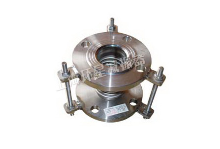
The outline of the installation and selection of the BW stainless steel bellows In the application of power pipe net and urban centralized heat-providing pipe net, stainless steel bellows is evidently superior to conventional compensating method. However, the pipeline project is quite complex due to the restriction of all kinds of external condition. Under different circumstances, the right selection of bellows is very important to safe operation and economy. The selection of bellows can be carried on as following steps: 1 According to the actual condition of pipeline, confirm the form and quantity of the bellows reasonably. Straight pipe sections fits axial expansion joint; L-tube sections, Z-tube sections fits one-way hinge type, double-free type and double-hinge-type expansion joint; While space segment fits double-fence type and single-angle, double-angle type universal joints to the expansion joint. 2 Select the material and confirm the level of working pressure according to the temperature of medium and make necessary modification as well.3 Calculate the displacement of every part to confirm the compensating quantum. The expanding or shrinking quantum of the pipeline caused by the temperature fluctuation can be calculated as follows: △X=CL (Tmax-Tmin) △X——line displacement(volume expansion) mm;C——pipe expansion coefficient mm/m0C; Tmax——maximum service temperature 0C;Tmin——minimum service temperature 0C; expansion coefficient of carbon steel materials:
| 工作温度℃ working temperature | 20-110 | 20-200 | 20-300 | 20-400 | 20-600 |
| X10-6 | 8.7-11.1 | 8.5-11.6 | 10.1-12.2 | 11.5-12.7 | 12.9-13.2 |
4、设置固定支架:它的作用是将管线分段设置固定点,保证波纹膨胀节在两个固定支架之间管段正常工作。固定支架由分为主固定支架和次固定支架。 主固定支架承受管线内压力产生的盲板推力,在管线的盲板端、拐弯、变径、支管进出口及装有阀门处都应设置。主固定支架主要承受三个力: (1)育板推力Fp=P?A;P——最高工作压力MPa;A——波纹管有效面积mm2;(2)膨胀节位移时产生的刚度反力Fk=1/2 K?e;K——刚度N/mm2;e——补偿量mm;(3)摩擦反力Ff=9.8μ(wL+wP);μ——摩擦系数;W——每米管重Kg/m;L——管线长 度m;wp——膨胀节重量Kg。由于后二者(2)(3)相比育板推力(1)小得多,一般可只粗略计算Fp。次固定支架不承受管线内压力产生的盲板推力,只承受膨胀节刚度反力和摩擦反力。5、按标准规定设置导向支架。膨胀节的安装:为保证波纹管膨胀节在工作温度下处于良好的工作状态,减少管架受力,安装前要进行预变形,凡属轴向膨胀节的轴向预变形量△L预由下式确定: △L预=X(1/2) X——轴向补偿量mm;Te——安装温度0C;Tmin——最低设计温度0C;Tmax——最高设计温度0C;△L预为正值,表示预拉伸量,△L预为负值,表示为预压缩量。安装注意事项:1、膨胀节安装前应先检查其规格型号与管道压力、直径、位移量等配置要求是否符合。2、带内筒的膨胀节安装方向与介质流向要一致。铰链型产品转动平面与管道位移平面是否一致。3、需要"预紧"的膨胀节,去所用的辅助构件,螺栓、螺母等在安装完毕后需。4、安装过程中,严禁用波纹管变形来调整管道安装误差。特别是法兰孔不对中时,可采用活套法兰和转动法兰,保证膨胀节处于自然状态,以患产生高压力,降低使用寿命。5、膨胀节所有活动元件一套有足够的活动空间,不得卡死。6、安装轴向补偿器时,必须保证与管道的同心度。7、 当波纹管需安装在动力设备进出口时,宜采用减振型不锈钢波纹管或带内罩型波纹管。严禁拆除产品拉杆(作运输防变形用除外),在压力较高时,需加强拉杆、支 耳强度,并在波纹管近端设置足够强度和刚度的主固定支架,在升压至工作压力后将两侧拉杆螺母调松至支耳2~5mm距离内。8、当安装在伸缩缝其大位移补偿时,可加大波纹管长度或采用复式轴向型式:如BW-FFL,BW-FL,BW-XL等。当要求较高时,也可采用BW-DJ型、BW-WJ型等加长型角向波纹补偿器和轴向型波纹补偿器组合串联使用。9、膨胀节可用于高频低振幅振动系统。为避免与系统发生共振,膨胀节的自振频率应小于系统频率或至少大于1.5倍系统频率。 单式膨胀节轴向振动自振频率fn=Ci Kx/W 式中W——波纹管和介质总重量kg;Kx ——波纹管轴向刚度N/mm,Ci——对于前五阶振型,Ci取值见下表:
4 Set up fixed bracket: it is used to divide the pipeline, set up fixed point to ensure the smooth operation of the corrugated compensator between the two brackets. The fixed bracket can be classified as primary and secondary. The primary bracket bear the blind plate thrust from the inner pipeline and it should be set up at the blind plate end, turning, track, and in-out port and where is installed valve. The main fixed bracket bears three kind of force: (1) blind plate thrust Fp=P?A;P——highest working pressure MPa;A——effective area of bellows mm2; (2)the counterforce of the rigidity caused by the expansion joint displacement Fk=1/2 K?e;K——rigidity N/mm2;e——compensation mm;(3)anti-friction force Ff=9.8μ(wL+wP);μ——friction coefficient; W——weight per meter pipe Kg/m;L——pipeline length m;wp——expansion joint weight Kg. Since the latter (2) (3) is much less than (1), Fp is a rough calculation. The secondary fixed bracket can only bear the counterforce of the rigidity and anti-friction force but not blind plate thrust caused by pressure pipeline. 5 Set up the guide bracket according to standards The installation of the expansion joint: To make sure the expansion bellows are in good working condition under the working temperature and reduce the force of the bracket, pre-deformation should be performed before installation. Pre-axial deformation can be determined by following formula: △L pre =X(1/2) X——axial compensation mm;Te——installation temperature0C;Tmin——Minimum design temperature0C;Tmax——the maximum design temperature0C;Positive △L预 means the volume of pre-tension while negative △L预 means pre-compression.Installation Notes: 1 Model specifications and configurations as pipeline pressure, diameter, and displacement should be checked before installation of expansion joint.2 The direction of inside-tube expansion joint should be consistent with medium flow. Confirm the rotation planes of the hinge-type products are consistent with the displacement of the pipe. 3 Auxiliary components used to retighten the joint, such as bolt, nut, should be removed and installation.4 Forbid to adjust pipeline installation error with bellows deformation. Especially when there are wrong holes in the flange, looper flange and rotating flange can be used to ensure the expansion joint is in a natural state in case high pressure reduces the service life. 5 Make sure the enough space for all movable element of the expansion joint.6 Guarantee the concentricity with the pipeline when installing the axial compensator.7 When the bellows need to be installed in the access port of the power equipment. Stainless steel bellows-type damping and cover-band-shaped bellows is recommended. Forbid to remove pull rod (except in the use of transport and anti-deformation).When the pressure is high, the pull rod and Supporting ear should be Strengthened .Besides, the main fixed bracket with enough intensity and rigidity should be set near the bellows. When the pressure rises to working level, the nut on both sides of the pull rod should be loosened 2~5mm within the distance of the supporting ear. 8 When large displacement compensation is needed, the length of the Bellows can be increased or double-axial type can be used ,such as BW-FFL,BW-FL,BW-XL. Prolonged angular corrugated compensator, such as BW-DJ, BW-WJ, and axial-type bellows compensator can be assembled and utilized in series when the requirement is high.9 Expansion joint can be used in the high-frequency and low-amplitude vibration system. To avoid resonance with the system, the natural frequency of the joint should be less than system frequency or at least 1.5 times greater than the system frequency. Natural frequency of axial vibration of single expansion joint fn=Ci Kx/W Where W——the total weight of medium and bellows kg;Kx ——axial rigidity of bellows N/mm,Ci——for the first five-order vibration mode,Ci values in the table below:
| 波数 Wave number | C1 | C2 | C3 | C4 | C5 |
| 1 | 14.22 | ||||
| 2 | 15.3 | 28.8 | 37.17 | ||
| 3 | 15.69 | 30.25 | 42.64 | 52.29 | 58.25 |
| 4 | 15.69 | 30.73 | 44.73 | 56.96 | 66.94 |
| 5 | 15.78 | 31.06 | 45.7 | 59.22 | 71.12 |
| 6 | 15.78 | 31.22 | 46.18 | 60.34 | 73.38 |
| 7 | 15.78 | 31.38 | 46.5 | 61.14 | 74.99 |
| 8 | 15.78 | 31.38 | 46.82 | 61.47 | 75.79 |
| 9 | 15.78 | 31.38 | 46.82 | 61.95 | 76.43 |
| ≥10 | 15.78 | 31.38 | 46.98 | 62.12 | 76.91 |
单式膨胀节横向振动自振频率fn=Ci(Dm/Lb) Kx/W 式中W——波纹管和介质总重量kg;Dm ——波纹管平均直径mm;Lb ——波纹管的波纹长度mm;Kx ——波纹管轴向刚度N/mm,Ci——对于前五阶振型,Ci取值见下表:
Natural frequency of transverse vibration of single expansion joint fn=Ci(Dm/Lb) Kx/W Where W——the total weight of medium and bellows kg;Dm ——the average diameter of bellows mm Lb ——the length of the corrugated bellows mm ;Kx ——axial rigidity of bellows N/mm,Ci——for the first five-order vibration mode,Ci values in the table below:
| C1 | C2 | C3 | C4 | C5 |
| 39.91 | 109.74 | 214.01 | 355.61 | 531 |


ZTA、ZTB、ZTC型阻尼弹簧隔振器
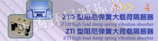
ZTD、ZTI型阻尼弹簧大载荷隔振器
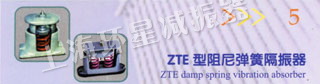
ZTE型阻尼弹簧隔振器
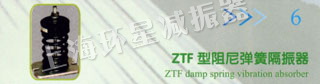
ZTF型阻尼弹簧隔振器
ZTG型可调式低频弹簧隔振器
LQT型金属弹簧隔振器(冷却塔专用)
DND大挠度金属弹簧隔振器
FXG型非线性金属弹簧隔振器 GSF型钢丝绳隔振器
ZDH、ZHS、VHS型吊式阻尼弹簧隔振器
YDS型弹簧隔振器
KT型空气弹簧隔振器
WHD型吊式橡胶隔振器
RM型橡胶隔振器 BE型橡胶隔振器(船用)
JG型橡胶剪切隔振器 JSD型低频橡胶隔振器
GDJ、T型橡胶隔振器 SPR抗冲击液压缓冲器
YZT型橡胶隔振器(电子仪器仪表用)